| Topkapi Installation Technical Notes |
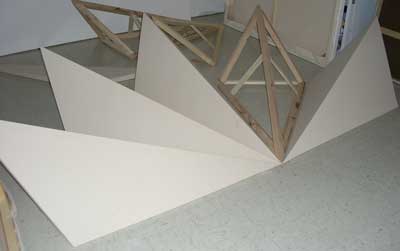
The purpose of this document is to describe the design of the three dimensional spires, which
are part of the Topkapi Installation, shown in Figure 1 below.
For comments on this material, please contact the artist: susan@susanbarnett.net
Figure 1 Topkapi Installation
The spire images on the canvases have the basic dimensions of 60” for the spine and 43.5” for the side, as
shown in figure 2. Each spire has a 36° angle from side-to-side, permitting 5 full spires (5 x 36 = 180) to form a
semi-circle, as shown in the grouping above the canvases in Figure 1. These dimensions are the only known
quantities for the design of the 3-D version of the spire. The 3-D design must maintain these dimensions on the
2-D projection to match the canvas drawings. An additional requirement for the spire was to maintain square
cross sections to simplify its design and construction.
To derive the angles and lengths for the 3D spire the starting point was the 2D bottom view in Figure 3, which
formed an isosceles triangle. Bisecting the 36° angle forms a right angle with the “base” of the isosceles
triangle. Since the angle and one side of the right triangle are known, it is possible to compute the other side,
X. 2X is a critical length for the spire, as it defines the widest point and is the length of the bottom brace of the
resulting form.
18° was chosen as the elevation of the spine from the horizontal, as shown in the side view of Figure 3. 18°
was the first choice, due to its prominence in the Topkapi patterns. It proved a fortunate guess. The resulting
right triangle in the side view was a 90° rotation from the horizontal plane of the bottom view. The front view
of Figure 3 is another isosceles triangle, with two sides Z and a base of 2X. Bisecting the top angle forms two
right triangles since it is an isosceles triangle. From the side view and the bottom view the length of two sides
of the formed right triangle is X. Since both sides of the formed right triangle are equal, the opposite angle is
45°. Using a shortened version of the Pythagorean theorem when two sides are equal, the hypotenuse is
computed by multiplying the side by the square root of 2. In the front view since one of the angles of the
formed right triangle is 45°, the top angle of the front view of Figure 3 is 90°. This 90° top angle is critical to the
design; it permits use of standard cross sections of wood to construct the spine for the spire.
The next step is to compute the angle α (alpha) formed from the bottom side to the spine. This angle is shown
in the 3D top view of Figure 3. The known quantities are Z from the front view, the length of the bottom side
(43.5”) and the formed isosceles triangle. The two equal sides of the isosceles triangle are the hypotenuse of
the triangle in the side view and the bottom side of the spire. The formula for computing α is shown in Figure 3.
The remainder of the angles and lengths of the spire are computed using similar techniques. Though not
“intuitively obvious to the casual observer” (math humor), the proofs are omitted to avoid complete boredom for
the reader. The completed design of one side of the 3D spire is shown in the 3D top view. To be
mathematically correct the length of the spine should be longer than 60” (63” to be exact). An artistic decision
was made to use 60” for the spine due to the viewing angle.
A side view of a completed spire is shown in Figure 4.
One other technical item: the right canvas of the installation is 5 feet in length. Three feet was chosen as the
distance from the wall for the right side to form another convenient right triangle: the 3 – 4 – 5 right triangle.
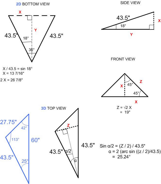
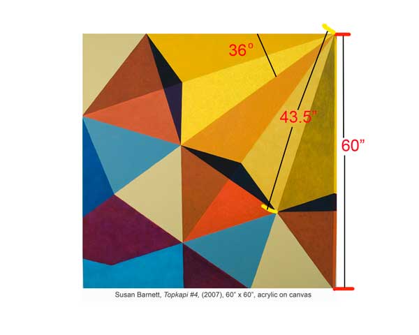
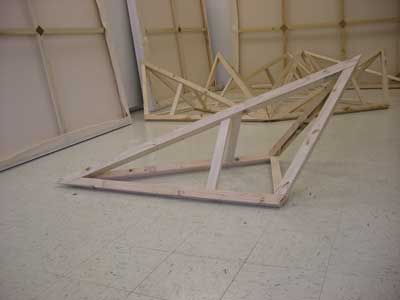
Figure 2 Topkapi Canvas #4
Figure 3 Mathematics of the Design
Figure 4 Completed Spire Frame
© copyright Susan Barnett 2002-2024